
iPhone 18 Pro Max Touch, Display and Graphics Section Schematic – KiCad Documentation
Modern smartphone display systems involve multiple power rails, high-speed communication interfaces, touch-control signals, and dedicated power-management circuits.
As part of my smartphone hardware reverse-engineering and technical training activities, I have created a conceptual iPhone 18 Pro Max Touch, Display and Graphics Section Schematic using KiCad.
This documentation focuses on the connections between the display power management IC, CPU, PMU, and the display/touch connector.
About This Project
The objective of this project is to represent the major components and signal connections involved in the iPhone 18 Pro Max touch, display, and graphics section in an organized schematic format.
The schematic was designed using KiCad EDA 10.0.4 and is intended to support circuit identification, signal tracing, power-rail understanding, and advanced smartphone hardware education.
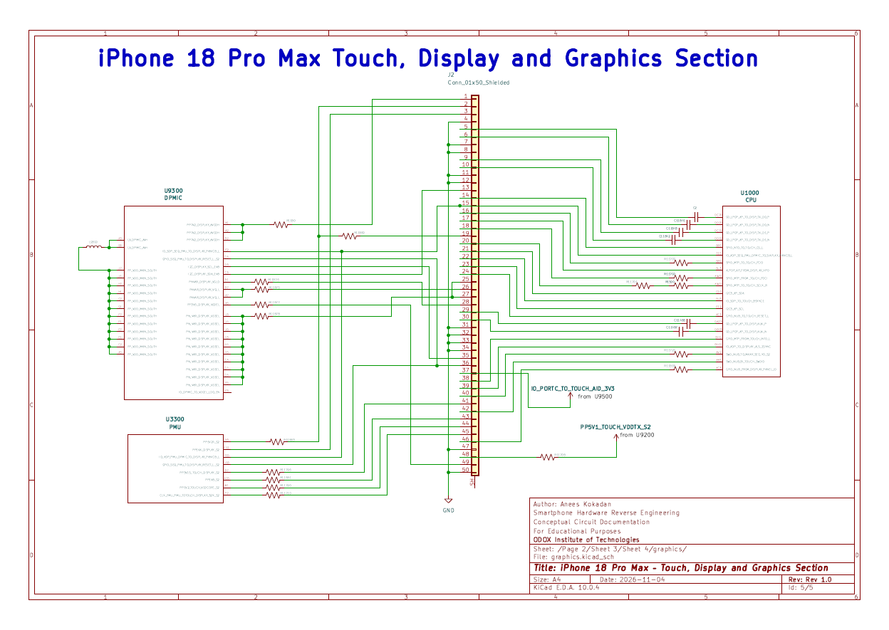
Figure 1: iPhone 18 Pro Max Touch, Display and Graphics Section – Rev 1.0
Major Components in the Schematic
1. Display PMIC – U9300
The DPMIC block contains display-related power connections and control signals. It includes display supply rails, switching connections, I2C control, reset, and display panic signals.
2. CPU – U1000
The CPU block represents the application processor interface to the display and touch section, including display data, touch communication, and control signals.
3. PMU – U3300
The PMU section includes several power supply and control connections associated with the touch and display architecture.
4. Display Connector – J2
The schematic uses a 50-pin shielded connector (Conn_01x50_Shielded) to represent the interface between the mainboard and display assembly.
Important Circuit Sections and Signals
1. Display Power Supply Section
The DPMIC and PMU sections contain several display-related power rails. Some of the important nets identified in the schematic are:
- PP7V2_DISPLAY_AVDDH
- PP3V5_DISPLAY_VDDEL
- PNVAR_DISPLAY_VGLO
- PNVAR_DISPLAY_VGLL
- PN_VAR_DISPLAY_VSSEL
- PP1VX_DISPLAY_S2
- PP3V15_TOUCH_DISPLAY_S2
- PP1V8_S2
- PP1V2_TOUCH_VDDCORE_S2
These power-net labels provide a useful starting point for studying the different supply connections in the display and touch architecture.
2. Display Data Interface – LPDP
The CPU-to-display interface includes differential display data signals identified by the LPDP naming convention.
- 90_LPDP_AP_TO_DISP_TX_D0_P
- 90_LPDP_AP_TO_DISP_TX_D0_N
- 90_LPDP_AP_TO_DISP_TX_D1_P
- 90_LPDP_AP_TO_DISP_TX_D1_N
- 90_LPDP_AP_TO_DISP_AUX_P
- 90_LPDP_AP_TO_DISP_AUX_N
- ALPDP_AP_FROM_DISPLAY_HPD
These signals are useful for understanding the display data and auxiliary interface connections between the application processor and display.
3. Touch Communication Interface
The schematic also identifies several touch-related communication and control signals.
- SPI0_NTO_TO_TOUCH_CS_L
- SPI0_MTP_TO_TOUCH_PCIO
- SPI0_MTP_FROM_TOUCH_POCI
- SPI0_MTP_TO_TOUCH_SCLK_R
- I2C3_AP_SDA
- I2C3_AP_SCL
- GPIO_NUB_TO_TOUCH_RESET_L
- GPIO_MTP_FROM_TOUCH_INT0_L
- GPIO_NUB_FROM_DISPLAY_PANEL_ID
4. Display Control Signals
Some important control connections identified in the schematic include:
- IO_SOP_SEQ_PMU_TO_DISPLAY_PANICB_L
- GPIO_SEQ_PMU_TO_DISPLAY_RESET_L_S2
- I2C_DISPLAY_SCL_1V8
- I2C_DISPLAY_SDA_1V8
- CLK_PMU_PMU_TOTOUCH_DISPLAY_32K_S2
- IO_AOP_TO_DISPLAY_ALS_ZSYNC
5. Additional Touch Power Connections
The schematic also identifies additional touch power connections:
- PP5V1_TOUCH_VDDTX_S2 – From U9200
- IO_PORTC_TO_TOUCH_AID_3V3 – From U9500
- PP1V24_S2
- PP1V8_S2
- PP1V2_TOUCH_VDDCORE_S2
Why This Schematic Is Useful for Training
Understanding display and touch circuits is an important skill in advanced smartphone hardware troubleshooting.
This conceptual documentation helps students and technicians identify important ICs, understand connector pin assignments, follow power rails, and recognize communication and control signals.
It can also be used as a reference for studying the relationship between the application processor, display power management, PMU, and display assembly.
Download the Schematic PDF
iPhone 18 Pro Max – Touch, Display & Graphics
Download or view the Rev 1.0 conceptual schematic documentation in PDF format.
View PDF Download Schematic