
When you shift from 8-bit microcontrollers like AVR to ARM-based STM32, the first thing you notice is the increased complexity in configuring GPIO pins.
This is not a disadvantage — it’s actually the power and flexibility of STM32.
In this blog, we’ll break down all the GPIO configuration registers required to set a pin as input or output on STM32, along with the meaning of each value.
Whether you’re a beginner or transitioning from AVR, this guide will help you understand exactly why STM32 requires these configurations.
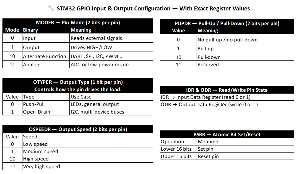
🟩 1. MODER — GPIO Mode Register (2 Bits per Pin)
Every GPIO pin in STM32 can operate in four different modes, unlike AVR which mainly has input/output.
| Mode | Binary Value | Description |
|---|---|---|
00 | Input | Reads external signal |
01 | Output | Drives 0 or 1 |
10 | Alternate Function | Used for UART, SPI, I2C, PWM, etc. |
11 | Analog Mode | Used for ADC or ultra-low power |
Example
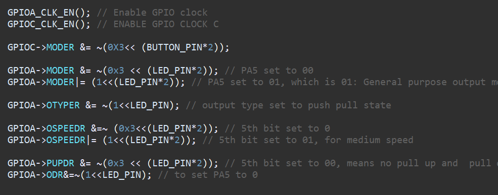
PA5 = 01→ OutputPC13 = 00→ Input
This register decides what the pin actually is.
🟦 2. OTYPER — Output Type Register (1 Bit per Pin)
Defines how the pin drives the output.
| Value | Type | Application |
|---|---|---|
0 | Push-Pull | General I/O, LEDs |
1 | Open-Drain | I2C, multi-device buses |
Example
PA5 = 0 → Push-Pull
STM32 provides open-drain at GPIO level, which AVR does not.
🟨 3. OSPEEDR — Output Speed Register (2 Bits per Pin)
Controls the switching speed of the pin.
Fast MCU clock speeds produce fast edges → which can cause EMI or noise.
| Value | Speed |
|---|---|
00 | Low Speed |
01 | Medium Speed |
10 | High Speed |
11 | Very High Speed |
Example
PA5 = 01 → Medium speed
This is important when driving communication lines or fast peripherals.
🟪 4. PUPDR — Pull-Up / Pull-Down Register (2 Bits per Pin)
STM32 pins are high-impedance.
So we must define how the pin behaves when nothing is driving it.
| Value | Meaning |
|---|---|
00 | No Pull-up / No Pull-down |
01 | Pull-up |
10 | Pull-down |
11 | Reserved |
Example
PA5 = 00→ No pull (output doesn’t need one)PC13 = 00→ Button has external pull-up on board
AVR only has internal pull-up; STM32 gives full control.
🟥 5. IDR & ODR — Input and Output Data Registers
These registers directly represent the logic level on the pin.
IDR — Input Data Register
Used to read input pin:
GPIOC->IDR & (1 << 13); // Read PC13
ODR — Output Data Register
Used to write output:
GPIOA->ODR |= (1<<5);   // Set PA5 HIGH
GPIOA->ODR &= ~(1<<5);  // Set PA5 LOW
These two registers are the heart of GPIO operation.
🟧 6. BSRR — Bit Set/Reset Register (Atomic Operations)
BSRR is one of the most powerful GPIO features in STM32.
It allows atomic, interrupt-safe pin updates.
| Operation | Bits Used |
|---|---|
| Set pin | Lower 16 bits |
| Reset pin | Upper 16 bits |
Example
Turn LED ON:
GPIOA->BSRR = (1 << 5);
Turn LED OFF:
GPIOA->BSRR = (1 << (5 + 16));
Unlike ODR (which is read-modify-write), BSRR updates only one bit safely.
🧠 Why AVR Never Needed All This?
Because AVR is:
- 8-bit
- Slow clock
- Limited pin functions
- No alternate function system
- No high-speed switching
- Only internal pull-up
STM32 pins must handle:
- High-speed communication
- Multiple roles per pin
- Noise/EMI handling
- Industrial interfacing
- Open-drain buses
- ADC/DAC
- PWM timers
This is why STM32 requires more detailed configuration—because it can do more.
🏁 Final Summary
To configure a GPIO pin correctly in STM32, we set:
| Register | Purpose |
|---|---|
| MODER | Select Input/Output/AF/Analog |
| OTYPER | Push-Pull vs Open-Drain |
| OSPEEDR | Control switching speed |
| PUPDR | Pull-up / Pull-down |
| IDR | Read the input |
| ODR | Write the output |
| BSRR | Atomic set/reset |
This fine-grained control is what allows STM32 MCUs to operate in professional, industrial, and real-time applications.